Category Archives: PCB - Page 2

Introduce of printed circuit board film

Film making is the previous printed circuit board or flexible pcb manufacturing process, the quality of film directly affects the quality of PCB product. In the production of a certain kind of PCB, it must have at least a corresponding film negatives. Each printed conductive pattern (circuit layer, the signal layer, the power level layer) and non-conductive pattern (solder mask and silkscree) should have at least one film negatives. By photochemical transfer of technology, the patternswill be transferred to the production pcb board.

Film negatives application in the PCB production for the following:

1. Photographic mask pattern transfer in the graphic, including circuits graphics and solder line graphics.
2. Screen Printing in the production of screen templates, including soldermask and silkscreen.
3. For Machining (drilling and milling appearance) based programming CNC machine tools and drilling information.

With the development of the electronics industry, the increasing higher of requirements of PCB. PCB design of high density, thin wire, small diameter tend to become increasingly fast, PCB production processes become more perfect. In this case, if no high-quality film negatives, can produce high quality printed circuit boards.In this case, if no high-quality film negatives, we can’t produce high quality printed circuit boards.
PCB development trends of advanced manufacturing technology

Summary of domestic and international manufacturing technology for the future development trends of PCB production is basically the same discourse: namely high-density, high precision, small hole diameter, fine wire, fine pitch, high reliability,multi-layered, high-speed transmission, lightweight, thin thickness development, and in production to improve productivity, reduce costs, reduce pollution and meet the many varieties and small batch production direction.
As printed circuit boards level of technological development, we often use the line width, diameter, thickness / diameter ratio as the representative. Please see the level of PCB development process as follows:

Level of development of printed circuit boards technology:

Years
 1970
 1975
 1980
 1985
 1990
 1995
 2000

Aperture (mm)
 1.0
 0.8
 0.6
 0.4
 0.3
 0.15

Width (mm)
 0.25
 0.17
 0.13
 0.10.
 0.08
 0.05

Thickness / aperture ratio
 1.5
 2.5
 5
 10
 20
 40

 Hole density, number of holes / CM2
 4
 7.5
 15
 25
 40
 55

CMD Circuits is engaging in manufacturing the high quality and competitive cost printed circuit boards and flexible pcb for our customers.

Methods of saving PCB cost

In order to let the cost of PCB can be as low as possible, there are many factors that must be taken into account:

1. The size of the board is most important. The smaller board, the lower the cost. Part of the PCB has become the standard size, as long as the cost according to size as it will naturally decrease.
2. SMT will be much lower than THT, because the components on the PCB will be more intensive (also small).
3. On the other hand, if the components on the board is very dense, then the routing must also be more detailed, and the equipments should be correspondingly higher required. The cost of these problems,compare to reduce the PCB size with more savings.
4. The more layers the higher the cost.
5. Drilling takes time, so NTHs the less the better.
6. Buried holes is more expensive than NTHs. Because the buried hole must be drilled at the junction.
7. Hole size.
8. Others.

Last, the equipments in manufacturing is more complicated, the cost will be more high. Understanding of PCB manufacturing process is very useful to save the cost. CMD Circuis have professional working group to analyze and control the cost of material.

The types of printed circuit boards

There are normal three basic types of printed circuits boards(PCB) are available.

1. Single-sided PCB

We have just mentioned, the basic PCB, components concentrated in one side, circuits are concentrated on the other side. Because the circuits only in one side, so we call this is single-sided PCB. Now only use this kind in the early stage.

2. Double-sided PCB

The circuits on the both side in this kind board. But with the circuit on both sides, the sides must have the appropriate electrical connections, the circuit between a “bridge” is called the plated through hole (via). PTH is in the PCB, the holes filled or coated with metal, it can be connected to the circuits with both sides. This kind more suitable for use in more complex products than the single-sided PCB.

3. The multilayer PCB

In order to increase the area for routing, multilayer spend more single-sided or double-sided circuit board. The number of multilayer PCB using  more double-sided PCB, and use the insulation between each layer to stick firmly. Board are several layers to represent the separate circuit layers, usually layers are even, and includes the outerside two layers. Most of the boards are 4 to 8 layer structure.

PCB silk screen plate making process

Please see the below  PCB silk screen plate making process:

1.Stretching

Stretching steps: network clean – the level of calibration – the bottom of plastic coated – Pop – Tension Measurement – coated adhesive – the net, Edge – Storage.

2.Drying net

Wash Network – Drying – use of premium film method – using light-sensitive adhesive (net pulp) – the choice of mesh lines – Film’s choice – exposing – Pressurized water wash and dry – use blue oilto cover – inspection, repair network, write the date of completion and the corresponding number and record keeping, storage.

3.Storage

Storage has generally adopted a vertical storage, network framework can be made or purchased, should be stored in the same environment with the screen environment to prevent deformation, while the screen before the need to test the tension on the screen, and test by the photographic film .

Silk-screen production steps

This time follow me to know the silk-screen production steps, how to mak e the silk-screen of printed circuits boards.

First, wash silk-screen

* Items required for washing silk-screen:
1, stripping water;
2, diluent;
3, detergent.

Second, coating

* Required coating materials: photoresist, scraper bucket, frame net sets.

Third, how to prepare light-sensitive adhesive.

Fourth, exposure.

Last, develop, wash csreen, drying and repair.

These are the silk-screen production steps, CMD Circuits has many years of experience of making printed circuit boards. Please contact us to know more.

PCB testing

This time let’s to talk about the PCB testing. When the printed circuit boards are finisehd, we should test PCB for short or open circuit condition, we can use optical test or E-test way to test.

Optical test methods identify defects in each layer by scanning, the electronic testing is usual using Flying flying-probe to check all connections. E-test for short circuit or open circuit much more accurate, but the optical test can more easily detect incorrectgap problems between conductors.

CMD Circuits have the very strict quality control and testing machines, please don’t worry about the quality of our circuit boards.

PCB copy board methods and steps

As you know, sometimes we will face to copy pcb as our customers just have the pcb circuit board samples in hand, no gerberfile. Please see below details of the PCB copy board methods and steps.

The first step, get a piece of PCB, keep records on paper of all molds, parameters, and location of the components, especially direction of diode, three machine and IC gap. Best to use digital camera to take photoes of the locations.

The second step, remove all the components, and remove the tin in PAD hole. Then use alcohol to clean printed circuit board, and then turn into the scanner,start POHTOSHOP, with a color screen to scan the silk screen side, save the file and print out.

The third step, use the water tissue paper to top layer and bottom layer minor sanding, grinding to a shiny copper film, into the scanner, start PHOTOSHOP, two color ways were swept. Note, PCB placed in the scanner must be horizontal level within the tree, otherwise the scanned image will not be able to use, and save the file.

The fourth step is to adjust the contrast of the canvas, with strong conparison between the copper film and no copper film part, then turn second picture to black and white color, check the lines are clear, if not clear, repeat this step. If clear, save the picture into black and white BMP format: TOP.BMP and BOT.BMP, if found in graphics problems can be repaired and modified with PHOTOSHOP.

The fifth step, turn these two files converted to PROTEL format, in PROTEL with two layers, if the PAD and VIA of two layers are on the same plase is means that the first few steps do well, if biased, then repeat the third step.

Sixth, Turn the TOP layer of BMP into TOP.PCB, attention should be transformed to the silk layer, that layer is yellow, and scan the top layer, and place the components according to the second step of the drawings.

Seventh step, turn the BOT layer of BMP into BOT.PCB, attention should be transformed into SILK layer, that layer is yellow, and scan the top layer. Deleted silk layer when finished.

Eighth step, Let TOP.PCB and BOT.PCB together in PROTEL, merged into a graph, it’s OK.

The ninth step, use a laser printer to print TOP LAYER, BOTTOM LAYER to a transparent film on the (1:1 ratio), put the film onto the PCB, compare to them, if right, you’re done .

Other: If it’s a multi-layer pcb, we should repeat the third to the ninth step, of course, named of the graphic is different, based on the number of layers. It’s much simpler to copy multi-layer double-sided pcb than multi-layer pcb.

Ok, these are the ninth steps of the double-sided pcb copy menthods, for more information, please contact us.

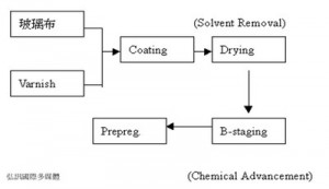
Prereg Making Process

Prereg also named “bonding sheet” (adhesive film), it’s the main part of the pcb substrate CCL, and made by glass fiber or other impregnated resin fibers.

Please see the blow form of prereg making process:

PCB substrate CCL

This time let’s to know the PCB substrate CCL. CCL also known as the PCB substrate. The reinforcement material impregnated with resin, one or both sides covered with copper, made by hot pressing into a  plate material, as copper clad laminates.

It is to do the basic PCB material, often called the substrate CCL. When it is used for multilayer circuit board production, also called core board (CORE).

FR-4 —- Flame Resistant Laminates,our material is now commonly used FR-4, also the most popular used for substrate.

Pages: Prev 1 2 3 4 Next